Summary

These pages summarise the work undertaken to try to see if it is possible to use a finite element analysis model to help understand the stress distribution in a large wide firebox boiler. The results presented stem from around 1,000 hours work, building/rebuilding models and applying different load cases.
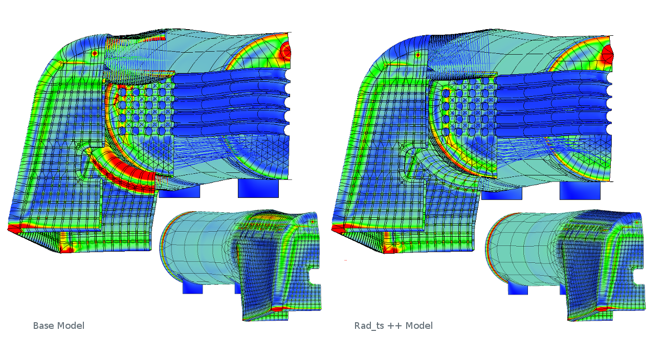
Variants of the model have been adapted to look at the effect of different stay patterns and plate thicknesses on reducing stress levels in the initial boiler design. The model has high stresses at the foundation ring corners and throat plate/combustion chamber transition. The latter may be exaggerated as a result of the modelling elements used but can be reduced with the introduction of the transition stays found in the original 118A boiler. However the resulting stiffening leads to higher thermal stresses on the firebox tube plate. Subsequent modelling work based around the Rad_ts model examines ways of reducing this thermal stress.
Every analysis presented here should be treated with a healthy dose of engineering scepticism! The geometric model is inevitably a simplification of the real world, as is the temperature distribution so it is quite likely that the results are not a true representation of the stress distribution in a real boiler.
However it is hoped that these theoretical results might provide some insight when coupled with practical boiler design and operating experience. Other areas of future theoretical study could include wrapper section profile to absorb firebox vertical expansion and smoke box tube plate flexibility.
These pages provide a limited view of the information contained in each model and the most benefit would be derived from seeing them in the native modelling software.
The work described has developed from an initial "I wonder if it could do this" exercise, detailed in the 118 page. This model is derived from an old general assembly drawing and, while not truly accurate, does contain a boiler of relevant dimensions, stay layout and material thickness. Building a model of this complexity was quite an undertaking but showed that results could be obtained on a medium sized laptop computer. This led to discussions as to whether a more accurate model of a wide firebox loco boiler would be useful. All of the other models contained in these pages are derived from a set of drawings that provide greater detail and accuracy of a modern steel fire box welded equivalent.
The software (called Mechanica) used for the simulations on these pages is about 20 years old and can only handle linear elastic material behaviour. It has been used extensively in aerospace and still exists today as the main analysis software of the PTC Creo engineering suite.
Areas of a typical locomotive boiler operate at the high end of the linear elastic range of the steel used. At times some components are likely to have been plastically deformed. This rightly leads to questions on the validity of this work but I feel it is still an interesting exercise in that the software can provide an indication of areas of stress concentration within the structure of the boiler and it is much simpler to try different things in software then it is to make modifications to a real operational boiler.
Stay failures would not happen if the boiler operated only at the stress levels prescribed in the various boiler standards. Those standards are based on pressure loads rather than thermal loads but the latter often appears to be the main cause of stay failures. If a boiler stay and margin configuration could be found that operated completely in the linear elastic range the analysis would be valid and the result of merit.
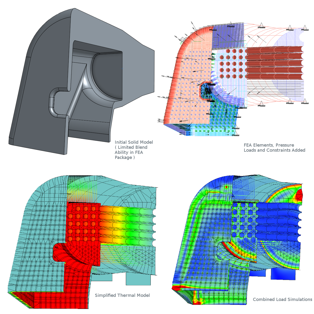
The model is a mid plate shell model. It would be impractical (on the computing resources available to me) to model all of the detail of such a big boiler in a geometrically complete CAD model. A shell model treats each plate as a surface with it's thickness as a property. A CAD model is still used as the basis of the analysis, mainly to overcome limitations in the corner blending capabilities of the FEA package. This model is then transferred into the FEA system and elements added. Unfortunately the automatic meshing does not work on such large models so 20,000 elements had to be added by hand over a period of weeks. The elements used are known as P-elements and the software automatically checks results accuracy by steadily refining the mathematics of the elements until a stable result is obtained
Two loads types are added to each model. The first is a pressure of 250 PSI ( 1.75 N/mm2). A thermal load is much more difficult to apply realistically. It is assumed that the fire box is uniformly 100 °C hotter than the outside of the boiler.
In truth the temperature distribution is much more complex. A more realistic approach would be to set the external temperature of the boiler to 200 °C and the firebox to 300 °C however this makes it more difficult to view the deformation of the boiler under the heat load because there are no stationary parts of the boiler to act as a reference. The heat load has been removed from the area at the base of the fire box where the grate would sit as this will shield that part of the firebox from the radiant heat. The load case used in all of the following simulations assumes that the temperature drops linearly along the tubes. This leads to very high stresses in the model and it is very likely that the reduction in temperature along the tubes is non-linear. I have run some of the models with a revised tube temperature profile that assumes a quicker reduction. The effect on the resulting stresses is very marked.
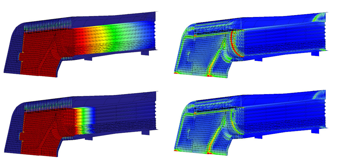
Unfortunately I used the upper tube temperature distribution in the above figure for all the subsequent pages before thinking more about the results and realising that the lower one might be a better representation. This means the thermal tube plate stresses in all the simulations are too high and each model needs to be modified and re-run before extracting the animations and stay plots for this website. I will update this when I can but it will take a lot of time to do.
Each variant of the model has it's own results page and menu entry at the top right of this web page. A full 3D web page display of the results is not practicable and so the information selected is a very small subset of that available in the model. Each results page has two switchable standardised views of the boiler and some graphs showing the maximum stress along selected stays. Both views can be animated to show (exaggerated 25 fold) how the boiler flexes under the applied thermal and pressure loads
The instructions on the images below work on subsequent pages but not on this one. The results web pages are large (~50MB) and will take some time to load on slower connections. A "spinner" will appear next to the page title while the background images are loading. Each page will be readable quite quickly but the animations will not work correctly until the page is fully loaded.
Each animation image is surrounded by controls as shown in the diagram below. These can display the results of the pressure and thermal loading separately or as a combined load
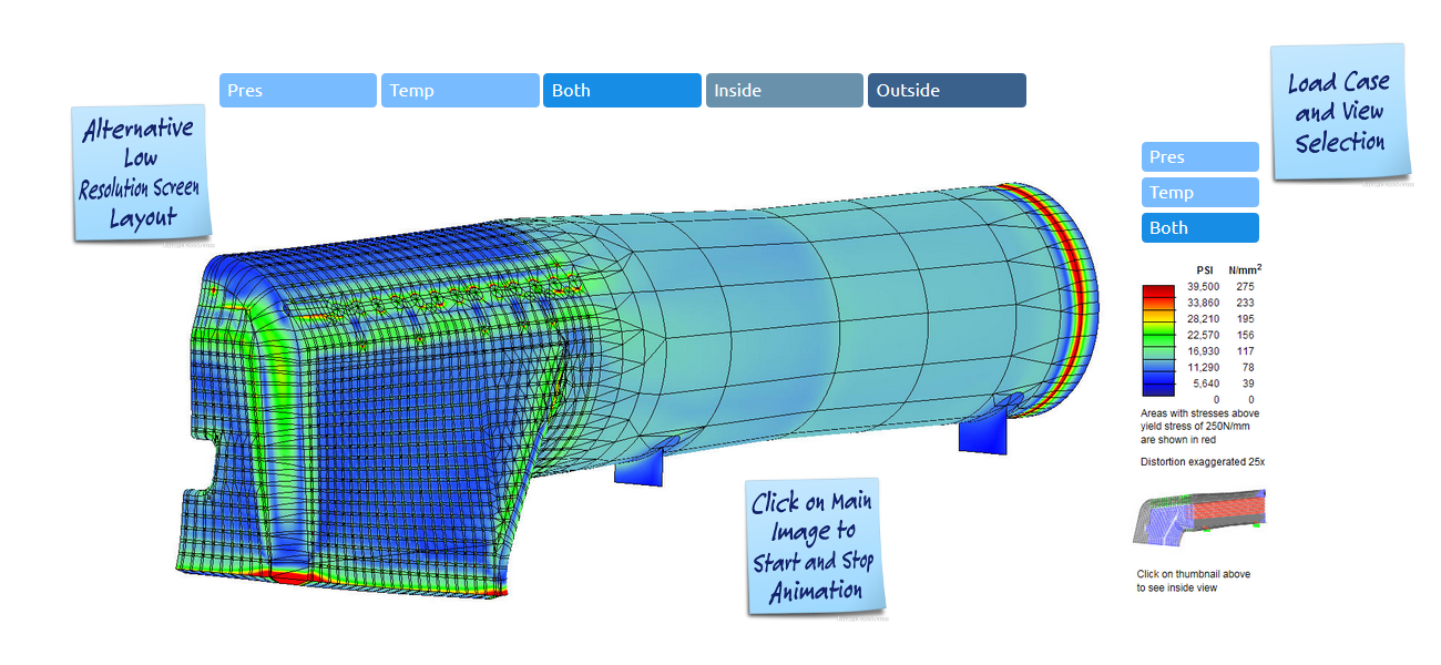
On lower resolution screens the legend is removed and the view and content controls move above the animation.
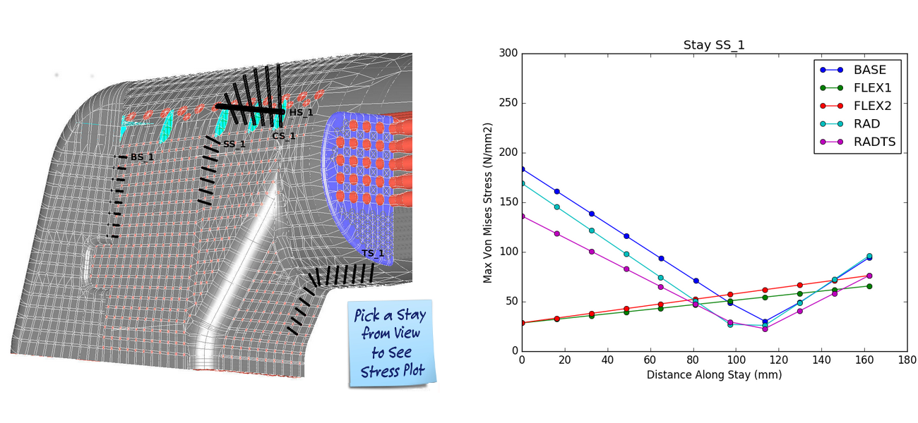
The stay plot shows maximum stress values along the length of the selected beam. Picking on one of the highlighted stays in the left hand image will change the plot on the right. (This works on the result pages rather than here).
The models use lines with a section property to represent stays (shown on the left below) rather than solid elements (right hand model below). This had to be done to make the model small enough to solve on the computing power available. The results need to be interpreted carefully as the shell/beam elements only show the maximum stress in any cross section.
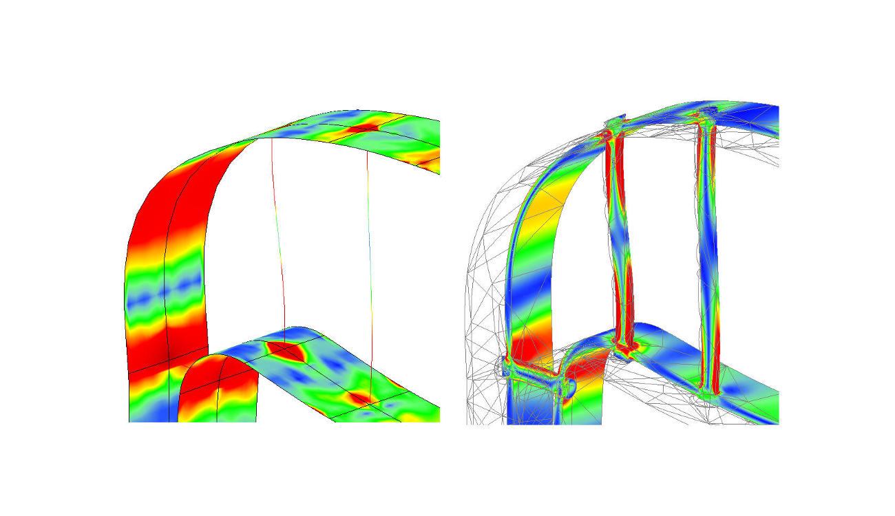
This can be very misleading as the reported stress probably only exists in the outer edges of the beam and may in reality be relieved by plastic deformation of adjacent areas allowing a greater cross section of steel to reach a higher stress level and support the required load. The design standards assume stays should not experience bending stress but in truth much of the stress in many stays comes from a bending load. The fact that the stress due to bending is at a maximum at the outer edges of a cross section through a stay might explain any necking or spalling that occurs before stay failure.
Six models are presented in the pages shown in the menu bar at the top of this page.
The 118 model represents an original P2 boiler with copper firebox.
The Base model is a more accurate representation of a welded equivalent.
Flex1 and Flex2 add flexible stays to the Base model.
The Rad model applies a different crown stay configuration to the Base model.
The Rad_ts model adds throat/combustion stays back into the Rad model.
Building models of this complexity is time consuming but a better option than building a series of experimental full scale boilers. It would be useful to verify the results against other analysis work on locomotive boilers but I have not found any other published work.
Lessons learned building the first models would help build further models in a more timely manner. These models could explore ways of using the pressure induced strain to accommodate differential expansion. An example of this might be a very small shape distortion to the wrapper over the fire box to allow it to expand upwards, reducing the tendency to expand downwards, twisting the foundation ring. This distortion might be achieved in reality by preloading the crown stays.