Base

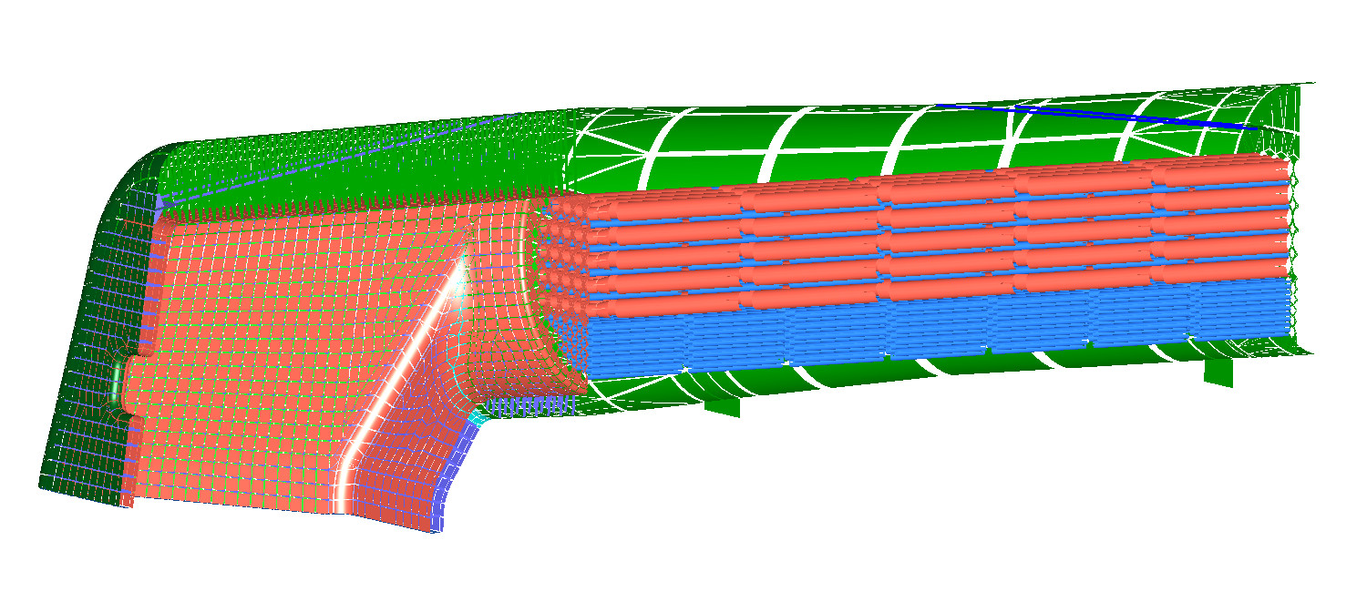
The base model is a geometrically accurate model of a welded all steel Model 118 boiler. There is some inaccuracy in the overall positioning of some of the stays but the stay spacing is correct. In this model none of the stays are flexible. This has been done to provide a baseline comparison with the 118 model and addition of flexible stays in the Stay1 and Stay2 models
The model results show high stresses in the foundation ring between the firebox throat plate and lower combustion chamber. Using the Pres(sure) and Temp(erature) buttons above to display stresses that result from each load type shows that the foundation ring stresses are mainly due to thermal loads and throat/combustion chamber loads are mainly due to pressure loading.
Animating the model by clicking on the main image shows the firebox lower edge effectively being pushed downwards by the greater expansion when compared to the outer wrapper. This effectively twists rather than bends the ring. I always assumed the stresses on the corners were due to bending stresses in the plane of the foundation ring but close examination of the animation reveals more of a torsional distortion. The foundation ring in a riveted boiler is typically deeper (to accommodate the rivets) and this depth is likely to be helpful in resisting such a twist. I do not know whether there is any slip between the riveted firebox plates and foundation ring that might help accommodate the differential expansion.
The high stress at the blend between the throat plate and lower combustion chamber plate is interesting. I'm not sure if this occurs in a real boiler, I've not heard of it before. It is a good example of an undesirable result of a pressure load helping reduce thermal stresses by allowing the lower half of the firebox tube plate to move backwards slightly. This can be seen when comparing pressure and temperature loads individually and in combination. The b118 model has stays in this area and does not show the same high stresses unless they are removed. The rad_ts model adds stays and these reduce the pressure induced stresses. However the stiffening of this area by the stays does not help from a thermal point of view, resulting in higher stresses in the firebox tube plate. I thought the magnitude of the stresses may be exaggerated through the use of beam elements rather than a tube shell model.
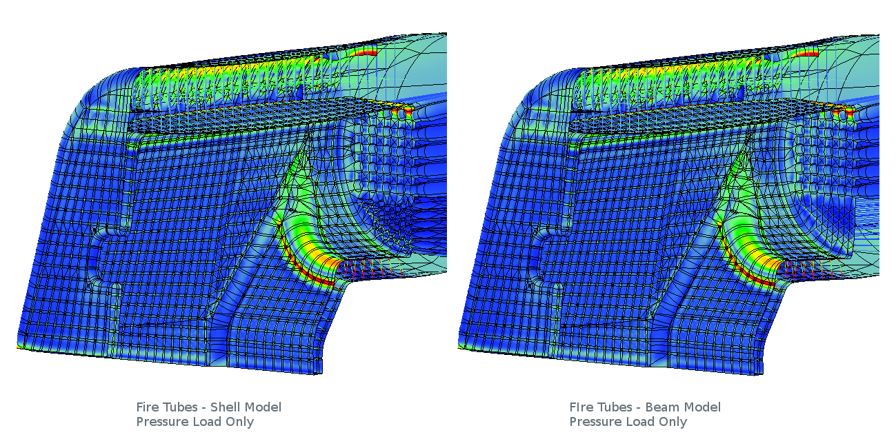
The base model was recently ( March 2018 ) rebuilt with full fire tube nest modelled with shell rather than beam elements. The plot above indicates that the use of beam elements did not materially change the stresses predicted at the throat/combustion intersection.
High thermal stresses are found in both tube plates. The thermal load model is not accurate so the absolute values should be treated with some scepticism. However the barrel is at a lower temperature than the firebox and tubes. Their respective cross sectional areas are also large. The tubes act to stiffen the centres of both tube plates leaving their outer margin as the "softest" area and likely to absorb the most differential movement.
Animation of the model shows a tendency for the wrapper and firebox crown to sag under the pressure loading leading to some stress in the shoulders of the wrapper over the firebox, between the vertical stays and horizontal cross stays. The thermal load seems to help relieve this and the plate loads are high but probably not high enough to cause issues in a real boiler. The same cannot be said for stay stresses.
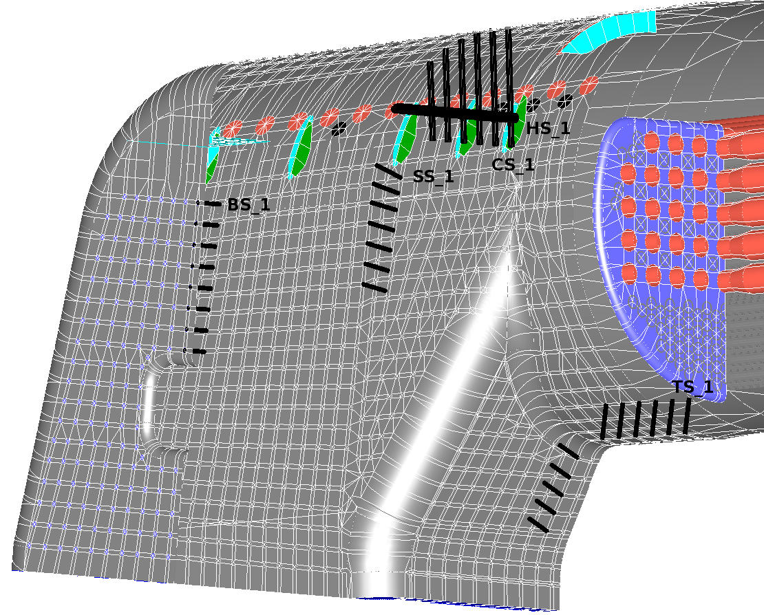
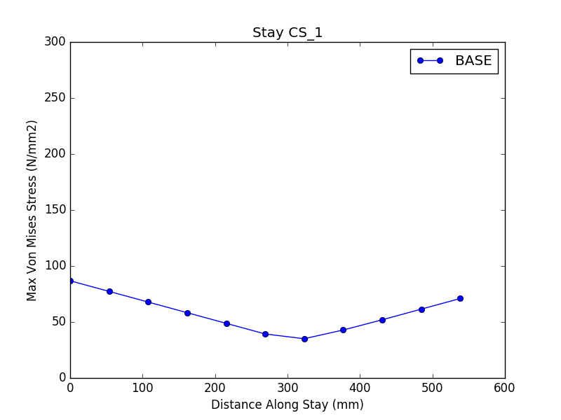
The maximum stress in a number of selected stays can be viewed in the graph above. All stays can be examined in the original model. The selected stays are typically highlighted in the image to the left of the graph. Picking a stay from here will show the maximum stress along its length. The zero point on the x-axis normally ( but unfortunately not always ) corresponds to the outer end of each stay. The hockey stick shape of each graph confirms the presence of bending stresses. The minimum value is the underlying tensile stress.
The stays (TS_1 to TS_11) adjacent to the combustion chamber and throat plate show very high peak stresses. This can also be seen in the stress plots on this page. These stays are trying to resist the backwards movement of the adjacent plates and are subjected to very high bending loads as a result.
Stresses in the side stays (SS_1 to SS7) are not as high. However they are roughly twice their design stress. SS1 shows the highest stresses (perhaps unsurprising as it is the top stay). Interestingly the side stay bending loads look to be increasing towards the foundation ring. A similar pattern can be seen in the back head stays ( BS_1 to BS_8 ). This does seem to fit the normal pattern for stresses to be higher in the upper stays but may be as a result of less support from a thinner foundation ring?
Crown stay stresses start fairly low with CS_1 but increase for stays further from the boiler centre line. This effect is seen when a cylindrical surface is used to support a flat surface with parallel vertical stays.
The Flex1 and Flex2 models look at the effect of flexible stays on the model.
