Launch 1 - Thames Umpire Launch Boiler

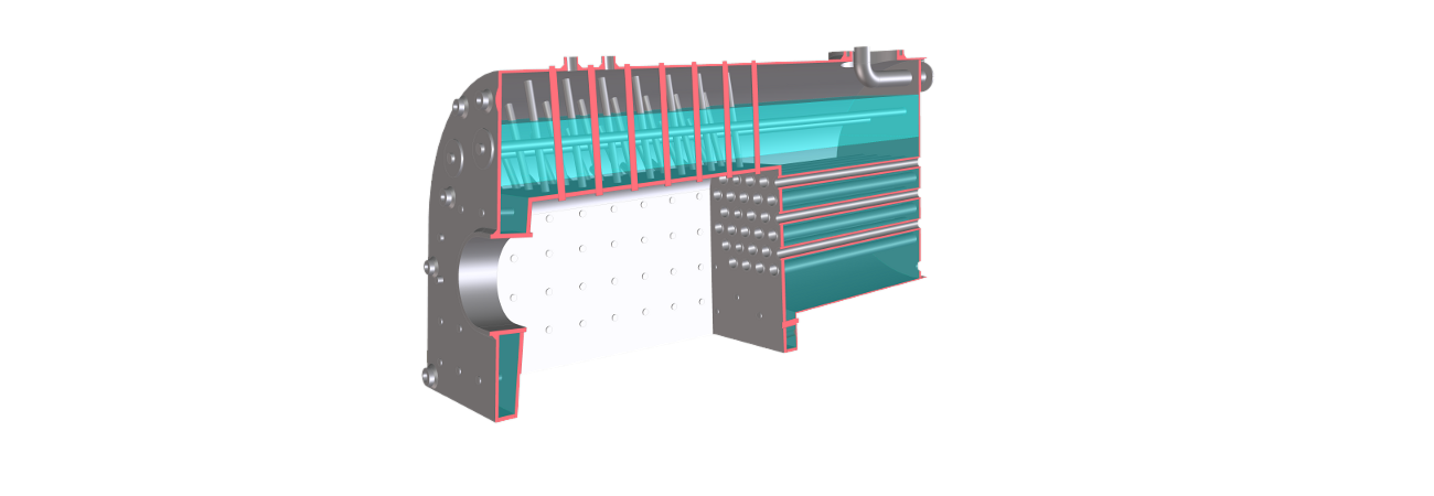
This model was built in 2012 and is of a new boiler for Consuta, a Henley umpire launch built by Sam Saunders in 1898 and restored in 2001. In 2017 the trust that operates her was awarded funding by the UK Heritage Lottery to replace her current boiler which is over engineered and 300 kg heavier than it needs to be. To save weight, Consuta's new boiler will use thinner plate than the original and has more steam space above the fire box crown.
The initial design used vertical stays to support the fire box crown. An early analysis, shown below, indicated some high stresses and distortion in the areas not supported by these stays.
The diagram's that follow warrant some explanation. Clicking on the main image will start an animation which shows an 50x exaggeration of the way the boiler flexes as it is brought up to its operating pressure (170psi) and down again (click on the moving image to stop the animation). The viewing angle can be changed by clicking on the small thumbnail to the right of the main image.
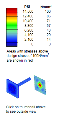
The colours on the surface of the boiler indicate the maximum stresses over the model. This type of display can be confusing as what is shown the just the maximum rather than the true distribution through the boilerplate. The top level, coloured red, is set to show areas that exceed a nominal yield stress of 39,000psi (250N/mm2). Blue areas have stresses below a nominal design value of 14,500psi (100N/mm2).
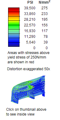
All that distortion and red colour look rather scary but it is important to remember that this is just a simulation and many approximations and assumptions have to be made when building the simulation model which has to be much simpler than the real boiler to be able to run on a modest sized computer.
One very visible example is the red areas around each stay attachment point on the half boiler models on this page. Their attachment stresses are exaggerated by the type of finite elements used (known as shell and beam elements). The stays (beam elements) assume they are spot welded to the wrapper (shell elements) at a single point rather than across the stay area. If the weld profile is modelled accurately using solid elements, as shown immediately below, these stresses are shown to be at much lower levels. Loco 2 is an example of a boiler simulated using solid finite elements.
The shell elements used also show bending stresses in a confusing way. Close inspection of the animated bread slice models below shows a more accurate picture of which side the bending stresses act.
Most locomotive boilers were designed before the advent of computers. Designs were typically only altered when something broke or bulged too much. Anything above the design stress but below the yield stress was likely to go un-noticed until some sort of fatigue failure occurred (stays being a prime example). It is also interesting to notice that the high stress areas are often some distance from the design problem that is causing them. This is evident at the rear corner of the wrapper plates.
The initial full boiler analysis showed that most of the distortion occurred in areas connected by the crown stays so a more detailed model was build to represent a vertical "bread slice" through the firebox.
This model highlighted the lack of support of the shoulders of the wrapper plates, allowing the horizontal component of the internal pressure to push them out. This can clearly be seen in the left-hand animation below.

This distortion could be reduced by adding horizontal stays above the fire box, but to save weight the analysis software was used to find a set of stay angles that provide adequate support without the need for extra stays. This is shown in the right hand animation above.
The stay angles in the initial full analysis model were then modified to those found with the bread slice analysis to provide a very much better stress distribution as shown below.
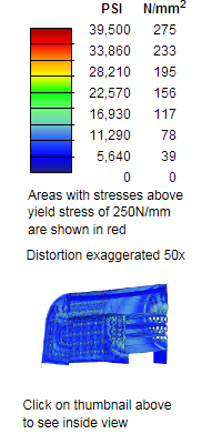
There is now very little movement in the boiler. The benefits of proper stay positioning are visible a long way from the wrapper. For example the junction between the throat plate and foundation ring shows less stress because the outer shell of the boiler is less distorted.
There is now very little movement in the boiler barrel but some further work could be done to balance the stay tubes and long stays to reduce back head and smoke box tube plate distortion.
This early analysis does not include temperature effects. Later models show that stresses due to differential expansion between the firebox and wrapper can be significant.